How to Sequence Retractable Roof Disassembly Safely
In January 2020, a worker was killed when a stadium roof structure collapsed during a snow-loading event at a venue in St. Petersburg — a catastrophic failure that investigators linked to compromised structural connections that the venue's maintenance history had not captured. Demolition engineers working on retractable roof systems face an analogous documentation challenge: the drive mechanisms, guide rail assemblies, and panel interlocks that enable a roof to open and close in service create load paths that standard structural drawings don't fully capture, and those undocumented load paths become the primary source of unplanned load release during disassembly.
Retractable roof disassembly sequence safety is a discipline that requires understanding not just how the roof was designed to carry load, but how it carries load in a partially disassembled state — when drive systems are disconnected but guide rails are still carrying panel weight, or when panels are removed in a sequence that concentrates wind load on the remaining structure. Getting that sequence wrong can mean a 50-ton panel assembly becoming unrestrained mid-lift. This analysis must be coordinated with the broader roof truss choreography sequence: the retractable panel system is structurally coupled to the primary truss below, and any load state created during panel disassembly affects the intermediate structural condition the truss must carry until the full system is removed.
Why Standard Demolition Sequencing Fails on Operable Roofs
Stadium operable roof deconstruction fails when project teams apply the removal sequence logic of a conventional fixed roof to a mechanically complex retractable system. A conventional fixed-roof truss is a passive structural system: remove the cladding, then remove the purlins, then remove the primary trusses in a sequence that manages unbraced length. A retractable roof is an active mechanical-structural hybrid: it has drive motors, cable tension systems, guide rail assemblies, emergency braking mechanisms, and panel locking pins that must be disengaged in a defined sequence before the structural disassembly even begins.
The MIT research on retractable roof technologies identifies three categories of load that a retractable roof panel carries in service but transfers differently during disassembly: gravity load (carried by guide rails and drive system in the open position), wind load (resisted by panel interlocks and locking pins in the closed position), and dynamic load from drive operation (absorbed by the drive mechanism and guide rail connections). Each of these load transfer paths must be explicitly addressed in the disassembly sequence — you cannot simply cut a retractable panel free at the primary structural connections without first accounting for what the guide rails and drive system are carrying.
The ScienceDirect wind effects research on retractable roof systems documents that partially disassembled operable roof structures can experience wind-induced loads significantly higher than those on the intact system, because the aerodynamic geometry changes as panels are removed and remaining panels are exposed to altered airflow patterns. This means the disassembly sequence must be designed for the wind loading condition of the intermediate state, not just the intact state.
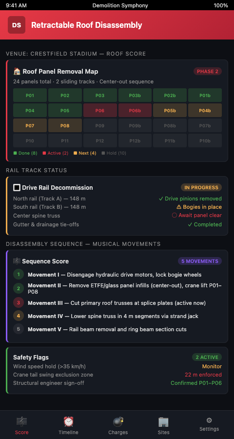
The Demolition Symphony Score for Retractable Roof Disassembly
Demolition Symphony Planner scores retractable roof disassembly as a multi-phase preliminary movement that precedes and enables the primary roof truss removal sequence: every salvage window, recycling stream, and structural cut becomes musical notation on a visual demolition score, and the mechanical disassembly measures run as a distinct staff before the structural staff begins. No structural lift can be scored until all mechanical disassembly measures in the same roof bay are marked complete.
The framework structures the disassembly across four movements.
Movement 1 — Drive System Deactivation and De-energization. The roof drive system — hydraulic, cable-driven, or rack-and-pinion — must be deactivated, de-energized, and locked out before any structural work begins. This is not simply an electrical lockout/tagout; it includes mechanical braking engagement, hydraulic pressure release, and cable tension relief in the sequence specified by the original drive system manufacturer. The MIT design considerations research for retractable-roof stadia identifies drive system deactivation sequencing as a safety-critical step that must be witnessed by a mechanical engineer with drive system expertise.
Movement 2 — Panel Connection Release in Sequence. Retractable panels are connected to each other and to the guide rail system at multiple points — panel interlocks, wind locks, travel stops, and drive attachment points. Releasing these connections in the wrong order transfers load from a connection that was designed to be released first to one that was designed to be released last, potentially exceeding the capacity of the remaining connections. The MDPI steel truss stability research establishes that connection release sequencing is as critical to temporary structure stability as member removal sequencing in conventional truss demolition.
Movement 3 — Panel Removal as Controlled Lifts. Each panel section is removed as an engineered lift with a site-specific rigging plan that accounts for the panel's actual weight (including accumulated debris and any residual drive hardware), its center of gravity, and its structural condition. The OSHA Technical Manual construction operations chapter requires that all overhead lifts on demolition sites be governed by a written rigging plan. Demolition Symphony Planner attaches the panel-specific rigging plan to each panel removal measure on the visual score.
Movement 4 — Guide Rail and Drive Hardware Removal. After all panels are removed, the guide rail assemblies, drive motors, cable sheaves, and ancillary mechanical hardware are removed as the final mechanical movement. These elements are often structurally attached to the primary roof trusses, and their removal may alter the truss load path — which is why the New England Metal Roof analysis of the Allegiant Stadium roof system identifies guide rail anchorage as a design feature that the structural engineer must evaluate before the primary truss removal sequence begins.
Advanced Tactics for Movable Roof Panel Removal
Three advanced tactics address the complexity that standard roof demolition planning underestimates on operable systems.
Complete the retractable roof disassembly before beginning the primary roof truss removal sequence. The temptation on an accelerated schedule is to begin primary truss removal at one end of the roof while retractable panel disassembly continues at the other. This creates a hazardous intermediate condition where the primary truss sequence has modified load distribution on one side while the panel system — still carrying wind and gravity loads — remains attached on the other. Demolition Symphony Planner enforces the completion gate: the retractable disassembly staff must be fully complete before the truss removal staff is permitted to begin.
Cross-reference the curved roof load paths analysis for panel removal sequencing. Curved geometry means that removing panels from the center of a retractable roof span produces different intermediate load conditions than removing from the ends. The load path analysis for the curved roof system — not the generic flat-roof retractable roof design documents — must govern the panel removal order. For stadiums where as-built structural drawings don't reflect post-original-construction modifications to the roof system, a pre-demolition scan-to-model survey may be required to establish actual load path geometry.
Apply temporary shoring discipline to guide rail structures. Guide rail assemblies span between primary structural frames and carry panel weight in service. As panels are removed and the guide rails become unloaded, they transition from structural elements to temporary structures that may require shoring to prevent racking or uncontrolled movement during the transition from loaded to unloaded condition. Temporary shoring logic from bridge deconstruction — specifically the practice of providing lateral restraint to primary structural members during the interval between partial and full removal — applies directly to guide rail assemblies in this configuration.
Delivering Safe Retractable Roof Removal
Movable roof panel removal at stadium scale is a retractable roof demolition engineering challenge that happens to use demolition equipment, not a demolition project that happens to involve complex mechanical systems. The distinction matters because it determines who leads the disassembly planning: a demolition superintendent working from standard roof removal protocols, or a structural and mechanical engineer working from a site-specific disassembly sequence validated against the actual load paths of the intact and intermediate-state roof system. Roof mechanism removal large venue projects add a layer of specialist coordination — drive system vendors, guide rail fabricators, and rigging engineers — that a conventional demolition team structure does not accommodate unless the project manager explicitly builds it into the organizational plan from the outset.
Demolition Symphony Planner exports the retractable roof disassembly plan as an engineer-validated scored sequence with mechanical deactivation steps, connection release order, panel rigging plans, and guide rail shoring requirements in a format that the demolition superintendent can execute in the field. Every mechanical step is a precondition for the structural step that follows. Every panel lift is backed by a site-specific rigging plan. Score Your Stadium Teardown with Demolition Symphony Planner and approach the retractable roof as the engineering-first operation it is.