Understanding Load Transfer During Partial Bridge Demolition
When Load Paths Shift Without Warning
The 2012 collapse of the Hongqi Viaduct during active demolition killed nine workers. A ScienceDirect study on domino-type progressive collapse traced the failure to load redistribution that the demolition sequence had not accounted for. When one span was removed, the forces it had been carrying transferred into the adjacent pier at a magnitude the original design had not assigned to that element. The pier failed, and the collapse cascaded.
Load transfer during partial bridge demolition is not a secondary consideration — it is the primary structural risk for every intermediate state between full bridge and complete removal. A bridge at 80% demolition is not 80% safe. It is a novel structure with load paths that never existed in the original design, supported by elements whose capacity margins are now unknown without specific analysis of that partial state.
NCHRP Report 458 on Redundancy in Highway Bridge Superstructures confirms that wider pier spacing reduces load redistribution capacity — meaning bridges with long spans between piers have fewer alternate load paths when one element is removed. For partial demolition stability analysis, that translates directly to higher risk per removal step, not lower risk just because fewer elements remain.
The standard tools — static load models, original design drawings, general structural notes — were calibrated for the complete bridge under service loads. None of them were built to analyze the bridge at an arbitrary mid-demolition configuration. Without a systematic way to track load state at each partial demolition step, teams make decisions based on incomplete information.
Scoring Every Load State as a Measure
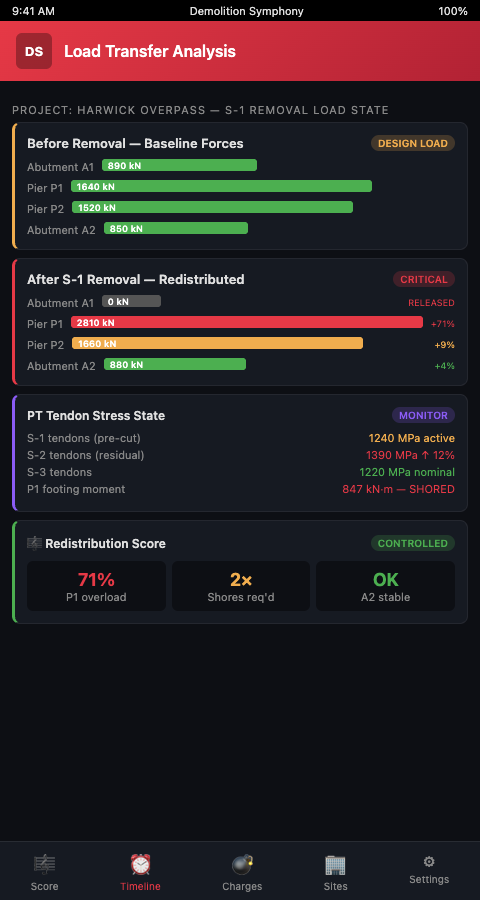
The Demolition Symphony Planner approaches load transfer partial bridge demolition as a score where each measure represents one structural state — one configuration of removed and remaining elements, with annotated load conditions at every load-bearing node. Just as a musical score tells each player not just what note to play but what the full ensemble sounds like at that moment, the demolition score tells each team member what the load picture looks like before and after their action.
The Load State Header. Every measure in the score opens with a load state header: which elements have been removed, which are shored, which are carrying full dead load, and which have been isolated. This header is the structural context that makes each subsequent action legible. An engineer reading the score for phase 4 sees immediately that pier 3 is now carrying the combined dead load of spans 2 and 4 — a condition that triggers a specific shoring requirement before any cutting begins.
Strut-and-Tie Substitutes. Darda's structural analysis guidance for demolition identifies substitute strut-and-tie models as the appropriate analytical tool for partial demolition states, because the original flexural model no longer applies once members are removed. The Demolition Symphony Planner encodes these substitute models as structural annotations within the score measure — visible to the engineer of record and traceable to the specific phase they govern.
Pier Load-Bearing Annotations. Each pier in the score carries a load annotation that updates as the sequence progresses. When span 2 is removed, the annotation on pier 2 and pier 3 updates to reflect the new tributary area each is supporting. Bridge pier load bearing is not static across phases; the score makes that dynamic explicit rather than leaving it to mental arithmetic on site. Teams that pair this with temporary shoring data can see the full picture of what is carrying load at any given measure.
Finite Element Validation Gates. The MDPI Safety and Stability Analysis of Railway Bridge Pier Demolition demonstrates that FEA validation at each staged removal step identifies capacity overruns before they occur. The planner integrates FEA validation as a gate between measures: the structural model for the next partial state must clear before the sequence advances. This is not just a documentation step — it is an active constraint that prevents the score from advancing past a structurally unsafe configuration.
Bearing and Joint Load Redistribution. When spans are removed in continuous-beam bridges, moments redistribute through the remaining deck. The FDOT Bridge Mechanics Reference Manual outlines how load distribution mechanics change under partial loading — knowledge that the Demolition Symphony Planner encodes as joint-level annotations within each phase measure. Field supervisors reading the score can see which bearing is now the primary load path at any given phase, and what its remaining capacity is.
Advanced Load-Transfer Tactics
Isolation before removal. Experienced teams do not remove a span and then check what happened to the adjacent load. They isolate the load path first — installing shoring or releasing bearings — before any structural element is cut. The score enforces this by writing the isolation step as a required note that precedes the removal note. A checker reading the score at any phase can verify that isolation is in the sequence, not assumed. Understanding the structural interdependence of multi-span bridges is the analytical prerequisite for isolation planning — until the load-sharing behavior between spans is characterized, the isolation protocol cannot be correctly sequenced.
Load redistribution to temporary supports. When a span is partially cut but not yet lifted, dead load migrates into the temporary support towers below. The Darda structural analysis for demolition confirms that load paths change as components are removed, and temporary support sizing must account for these transient load states, not just the final removal state. The Demolition Symphony Planner annotates each shoring tower with its governing load case, drawn from the phase in which the tower carries the most load — typically not the final removal moment but a mid-cut state.
Partial demolition with live traffic above. On overpasses where traffic remains on an adjacent lane during partial demolition below, dead load and live load interact at each intermediate state. CSiBridge staged construction analysis, as described in the CSI America documentation, models each partial demolition stage separately. The Demolition Symphony Planner captures these staged results as annotations on the live-traffic measures, making the load state visible to both structural and traffic teams simultaneously.
Redundancy mapping for each phase. NCHRP Report 458 classifies bridge redundancy in three types — structural, load-path, and internal. As demolition proceeds, each type of redundancy changes. The score includes a redundancy register per measure: which redundancy type is active, which has been eliminated by the removal sequence so far, and what that means for the risk level of the next step. This register gives the project structural engineer an immediate view of how much margin remains at each phase.
Connecting load transfer to pre-blast structural assessment. Teams familiar with highrise implosion work will recognize the phase-gate discipline from pre-blast assessment protocols, where each floor's structural condition must be confirmed before the charge placement sequence is finalized. Load-transfer verification in partial bridge demolition follows the same logic: confirm the structural state at each intermediate configuration before committing to the next removal action.
The Cost of Skipping the Analysis
The Hongqi Viaduct collapse is not a historical outlier — it is a documented example of what happens when structural load redistribution during partial bridge demolition is treated as something to manage instinctively rather than calculate explicitly. Nine fatalities. Unplanned collapse. And a project team that had no shared tool for tracking load state across phases.
Partial demolition stability analysis cannot remain the exclusive domain of the structural engineer's calculation set. Field teams making real-time decisions — on when to cut, when to release a bearing, when to advance the crane — need access to the same structural picture in a form they can read without a structural engineering degree. The Demolition Symphony Planner is built to bridge that gap.
When the analysis is skipped, the consequences compound across phases rather than occurring as a single event. A pier that absorbs a small over-load in Phase 2 without visible distress may carry that accumulated stress into Phase 3, where a second redistribution event pushes it past yield. No single phase looks catastrophic in isolation. The cumulative effect does. Tracking load state at every intermediate configuration — and annotating it in a shared score that every team member reads — is the mechanism that exposes these accumulation patterns before they become field emergencies.
Start with the Load State, Not the Schedule
Bridge and overpass demolition teams taking on partial removal projects should begin by mapping load states, not building Gantt charts. The Demolition Symphony Planner gives your team a score where every phase is legible, every pier's load annotation is current, and every gate between measures requires a structural confirmation before the sequence advances.
Load state mapping is not a one-time pre-demolition activity — it is an ongoing obligation that must be updated after each structural action and confirmed before the next. When the Demolition Symphony Planner is used from the first planning session, the load state map becomes the structural backbone of the entire project: every schedule decision, every crane positioning choice, and every traffic window selection is downstream of the structural reality it reveals.
Start your partial demolition planning with the Demolition Symphony Planner and build a score where every bridge span's load state is tracked, every pier annotation is updated at each phase, and every gate between measures requires a confirmed structural check — so your bridge and overpass demolition team never advances a phase before the load distribution has been verified safe.