Predictive Modeling for Cantilever Deflection During Staged Removal
Predictive Modeling for Cantilever Deflection During Staged Removal
When the cantilever roof of a stadium grandstand collapsed in Hartford, Connecticut in 1978 under an unexpected snow load, the post-failure investigation found that the structure had been operating well within its design envelope for gravity loads — but the snow created a distributed load case the cantilever's connection detailing could not resist (ASCE Cantilever Roof Structural Failure). Similar collapse mechanisms have been observed in cantilever roof structures across Europe, where snow-induced distributed loads combined with existing connection fatigue produced failures in structures that appeared sound under routine inspection. In a staged demolition, the same connection details that survived decades of service are suddenly being asked to carry redistributed loads they were never designed for — at precisely the moment when the structure has no redundancy left to absorb the unexpected.
Predictive modeling for cantilever deflection during staged removal is not optional for stadium demolition teams. It is the difference between a controlled phased deconstruction and an unplanned structural event during active work. Cantilever deflection analysis must also run in parallel with bowl stability analysis: the cantilever roof is anchored to the grandstand bowl, and each cantilever removal step changes the load distribution on the bowl rim below.
Why Cantilever Behavior Changes Radically During Staged Removal
A cantilever grandstand roof in service behaves as a statically determinate or mildly indeterminate structure carrying a predictable combination of dead load, live load, and wind. Its deflection under these loads is bounded by the design engineer's calculations, and the connections are sized to carry those loads with appropriate safety factors.
Remove the backstay elements — the rear columns or tie-backs that provide cantilever moment resistance — and the structure is no longer the same system. The large deflection behavior of a cantilever beam without backstay is genuinely nonlinear: as the tip deflects downward, the geometry changes, which changes the moment arm, which changes the internal force distribution (ScienceDirect Large Deflection Cantilever Beam). A linear elastic model that was valid for the original structure will underpredict deflection by a significant margin once the backstay is removed — and it is precisely in that underestimated range that connection failures occur.
Darda's structural analysis for deconstruction identifies this nonlinear transition as the key reason that pre-demolition structural assessments based on design-era calculations are insufficient for cantilever removal planning. A new analysis, using the current structural geometry and connection condition, is required for each staged removal phase.
FEA Cantilever Removal Stadium: Building the Phase Model
Finite element analysis is the established method for modeling cantilever deflection during staged removal because it handles geometric nonlinearity natively — the model updates the stiffness matrix at each load increment as the deflected geometry changes (Ansys What Is FEA). For a stadium cantilever roof, the FEA phase model must include:
Current connection condition. Design-era connection capacities will overestimate actual remaining capacity if the connections show fatigue, corrosion, or prior overload indicators. The structural survey must characterize each connection type and input reduced capacity values where deterioration is observed.
Sequential element removal. The model must simulate each removal event as a discrete step, updating the deflected geometry and redistributing loads before the next removal is applied. Applying all removals simultaneously will miss the intermediate load states that can govern connection demand.
Dynamic amplification for mechanical demolition loads. High-reach excavators and hydraulic shears generate impulse loads on the structure during cutting operations. These must be represented in the model as short-duration dynamic loads applied at the cutting location, not omitted from the static analysis.
Research combining FEA with deep learning has shown that prediction accuracy for cantilever deflection improves significantly when the model is trained on the specific connection geometry rather than using generic beam section properties (Exploratiojournal FEA + Deep Learning Cantilever). For a stadium with several different cantilever span lengths and connection types — as is common in multi-tier grandstand designs — this means running separate calibrated models for each span type rather than a single representative model.
Grandstand Deflection Monitoring Deconstruction: Connecting Model to Reality
The FEA model predicts deflection at each phase. The monitoring system measures it. The gap between prediction and measurement is the early-warning signal that the model needs updating or the phase plan needs revision.
Grandstand deflection monitoring during deconstruction typically uses a combination of total station surveys (for absolute position of key reference points), tiltmeters (for rotation at connections and mid-span), and strain gauges (for connection force demand). Survey frequency must match the demolition pace: if a removal event takes 4 hours, the monitoring cycle must be short enough to detect a deflection trend before the next removal begins.
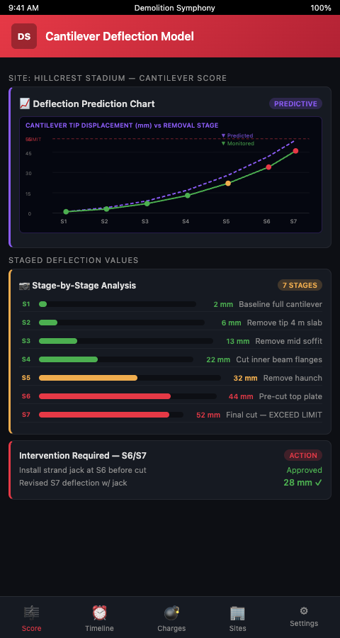
In the Demolition Symphony Planner, predicted deflection curves from the FEA model are embedded directly in the visual score as reference lines for each removal measure. When field monitoring data is entered after each measure, the score automatically flags any measured value that exceeds 85% of the predicted value — triggering a model review before the next measure can be approved.
Advanced Tactics: Staged Load Removal Cantilever Simulation
Two tactics consistently improve the accuracy and safety of staged load removal cantilever simulation:
Pre-removal load relief. Before removing a support element, apply a temporary load relief — using hydraulic jacks at the cantilever tip — to reduce the connection demand to near zero before the cut. This converts a dynamic removal event (sudden load redistribution when the support is cut) into a quasi-static event (load already redistributed before the cut). The deflection model must account for the jacked configuration, not the pre-jack configuration.
Incremental section removal. Rather than removing an entire cantilever bay at once, cut it into smaller sections starting from the tip and working inward. Each section removal produces a smaller load redistribution event, and the cumulative deflection after multiple small removals is more predictable than the single large deflection after removing the full bay. This approach also keeps the dynamic loads from each cut smaller, reducing the amplification factor applied to connection demand. The sequencing logic mirrors what seating removal care requires at the grandstand level: removing elements in an order that preserves the structural integrity of adjacent retained sections rather than exposing them to uncontrolled load redistribution.
The connection between cantilever analysis and bowl stability is direct: a cantilever tip deflection that shifts the anchorage reaction changes the bowl rim's load distribution — which can in turn affect the residual load path in the bowl sectors below. Both analyses must be updated in parallel at every removal step, not sequentially.
For teams managing debris trajectories alongside deflection risk, the lessons from debris trajectory modeling apply directly: a cantilever section that fails unexpectedly will produce a debris field that extends well beyond the planned exclusion zone, with trajectory determined by the final deflected position and the velocity at failure.
Practical Thresholds for Cantilever Demolition Sign-Off
FEA cantilever removal stadium models should output three threshold values for each removal phase:
- Advisory threshold (typically 60% of predicted maximum deflection): monitor frequency doubles, field engineer must be on-site during any further removals.
- Hold threshold (typically 80% of predicted maximum): all demolition activity stops, structural engineer reviews model against field measurements, temporary support is assessed.
- Evacuation threshold (typically 90% of predicted maximum or any unexpected acceleration in deflection rate): exclusion zone activated, structure assessed for emergency shoring before any personnel re-entry.
These thresholds must be project-specific, based on the FEA model output and the actual connection capacities from the structural survey — not generic percentages applied without engineering review.
Demolition Symphony Planner encodes these thresholds as color-coded gates in every cantilever removal sequence: green for proceed, yellow for advisory, red for hold. Stadium demolition teams managing complex grandstand deflection monitoring during deconstruction can Score Your Stadium Teardown with a platform that brings the FEA model and the field monitoring protocol into the same coordinated visual score.