How to Model Dust Cloud Propagation for City Block Containment
What Post-Blast Particulate Actually Looks Like at City Block Scale
The JHU study that measured PM10 at 3,000 times baseline levels was conducted under relatively favorable meteorological conditions: moderate wind speed, measured air sampling at multiple distances, a controlled research environment. Real urban implosions rarely happen under ideal conditions, and the dust plume behavior in variable wind, around multi-story buildings that create turbulent wake zones, or in conditions of low atmospheric mixing is substantially more complex — and more dangerous — than a simple Gaussian dispersion model predicts.
PM10 influence from building demolition extends 50-100 meters at low wind speeds, but that range expands significantly when wind increases or when large facade surface areas are exposed to the blast. A 40-story concrete tower releases substantially more respirable particulate per square foot of demolished floor area than a low-rise steel frame building, because the concrete itself shatters into fine fragments that remain suspended far longer than coarser debris. Silica and toxic metal dust from demolition exceed safe occupational exposure limits in the immediate post-blast window — and if the exclusion zone and shelter-in-place guidance has not been correctly calibrated to the dust propagation model, people at the perimeter receive occupational-level exposures.
The US demolition industry's scale — valued at $11.2 billion — reflects the frequency and scope of demolition work across American cities. With that scale comes a persistent pressure to treat dust modeling as an administrative task rather than a technical one. It is not. Implosion dust containment modeling and dust suppression implosion planning must be treated with the same rigor as charge design and delay sequencing — the dust cloud is a direct consequence of the collapse sequence, and its propagation is predictable if the input data is correct. Urban demolition particulate spread depends on the collapse geometry (which determines the initial particulate release), the building material composition (which determines the particle size distribution), and the meteorological conditions (which determine the transport distance). Dust cloud propagation city block demolition models that incorporate all three inputs produce actionable containment designs; models that assume standard conditions produce false confidence.
The Dust Cloud Propagation Modeling Framework
Think of the post-blast dust cloud as an instrument you must compose into the score before you can call the implosion finished. The charge sequence determines the debris footprint; the debris footprint determines the initial particulate release; the wind and atmospheric conditions determine how that release propagates to the city block boundary. All three components must be in the model before you know whether your containment measures — water cannons, debris curtains, shelter-in-place zones — are positioned correctly.
Step 1: Characterize the building's material composition. Dust generation and particle size distribution depend on what the building is made of. A reinforced concrete tower produces substantial fine silica particulate from the cement matrix. A steel frame building with lightweight concrete floors produces less. A building with historic terra cotta cladding may produce lead-containing dust from paint applied to the cladding decades ago. The material characterization determines the particle density, size distribution, and toxicity profile of the dust cloud — all of which affect the dispersion model parameters and the exposure risk assessment. The debris footprint prediction model uses the same material composition data as the dust model, so both analyses should be built from the same material characterization source rather than developed independently with potentially inconsistent inputs.
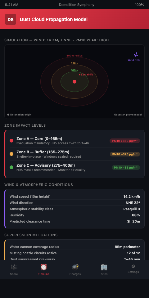
Step 2: Select the appropriate dispersion model for your site geometry. The Gaussian plume model is the standard for open-field applications. In an urban core, building-induced turbulence — the wake effects behind tall structures, channeling in street canyons, recirculation zones in building clusters — can significantly alter the plume trajectory compared to the open-field prediction. CFD models predict PM dispersion under multiple wind directions and account for building geometry effects that simpler analytical models cannot represent. For a 40-story implosion in a dense urban environment, a CFD-based dispersion model is the appropriate tool.
Step 3: Run the model for multiple wind scenarios. Wind direction and speed on shot day are not knowable weeks in advance. The dust propagation model should be run for at least four wind direction scenarios (from each cardinal direction), two wind speed conditions (low and moderate), and a calm-wind condition. The results define the envelope of possible plume extents and directions — which then defines the envelope of exclusion zone configurations and shelter-in-place guidance that may be needed on shot day.
Step 4: Design the dust suppression system to the model outputs. A cleaner demolition scheduling methodology integrates dust dispersion modeling into demolition scheduling optimization rather than treating suppression as an afterthought. Water cannon placement, debris curtain height and extent, and misting system coverage should all be derived from the dispersion model — positioned at the upwind and crosswind edges of the expected plume boundary for the prevailing wind scenario on shot day.
Step 5: Set the shelter-in-place radius from the model, not from the exclusion zone. The exclusion zone protects against debris impact. The shelter-in-place radius protects against dust exposure. These are different radii for different hazards, and they should be communicated separately to neighbors. The JHU study recommends that spectators position themselves upwind at a significant distance or shelter indoors within a 7.5-block radius. Your dust propagation model either confirms or revises that radius for the specific conditions of your shot.
Step 6: Integrate the dust model with the Demolition Symphony Planner implosion score. The sequence plan determines the debris footprint; the debris footprint is the source term for the dust model. When you adjust timing intervals to change the collapse mechanism — from directional fall to inward fold, for example — the debris footprint changes, and the dust model must be rerun. Demolition Symphony Planner connects the sequence timing to the dust suppression plan as a linked layer, so a timing revision that changes the debris footprint automatically triggers a review flag on the dust containment design.
Advanced Tactics: Post-Blast Monitoring, Silica Management, and Regulatory Documentation
Deploy real-time particulate monitors at the exclusion zone perimeter on shot day. PM10 and PM2.5 monitoring at the perimeter during and after the shot provides real-time data on whether the dust cloud is staying within the modeled boundary. If the perimeter monitor reads above threshold, the public information officer can immediately extend the shelter-in-place advisory rather than waiting for post-shot analysis. This real-time monitoring posture also creates the data record that demonstrates regulatory compliance.
Address silica exposure separately from general PM10. Crystalline silica from shattered concrete is classified as a human carcinogen at occupational exposure levels by IARC. The regulatory exposure limits for silica are substantially lower than for general PM10. If your dispersion model shows silica-containing particulate reaching the exclusion zone perimeter, the adjacent structure protection and shelter-in-place communications need to reference silica exposure specifically — not just "dust."
Connect the dust model to the debris footprint model. The debris footprint defines where primary debris lands. The dust cloud propagates from the entire demolition event — including the fine particulate that does not land within the debris footprint but travels further. These two analyses share a source term (the building's material composition and collapse geometry) and must be designed together, not independently. The fragmentation analysis for reinforced concrete towers provides the fragment size distribution that feeds both models — larger fragments define the debris footprint boundary while the fine fraction drives the dust dispersion source term.
Treat the Hilco incident as a design reference case, not just a regulatory warning. The Hilco dust cloud covered a residential neighborhood because the demolition proceeded without adequate dust suppression and without waiting for wind conditions that would have directed the plume away from the residential area. The technical lessons: the dust propagation model must be run before the shot date is fixed, the wind-dependent go/no-go threshold must be defined for dust exposure (not just debris direction), and the suppression system must be sized for the worst modeled scenario, not the average one.
Apply the modeling approach to the noise abatement scheduling challenge in stadium demolition. Noise and dust share a common planning structure: both are post-blast emissions that propagate outward from the source, both require modeling to determine the affected radius, and both require advance communication with affected neighbors. The CFD dispersion methodology for dust translates directly to acoustic propagation modeling for blast noise.
Include the dust propagation model in the permit submission package. Regulatory reviewers in jurisdictions with strict urban demolition ordinances increasingly require dust dispersion analysis as part of the permit application, not as a post-approval deliverable. Submit the model, the suppression design, and the monitoring protocol together as a unified air quality management plan.
Model the Cloud Before You Fire the Sequence
Demolition Symphony Planner gives urban high-rise implosion coordinators the planning framework to connect the implosion sequence, the debris footprint simulation, and the dust suppression design as linked layers — so every timing adjustment that changes the collapse geometry also triggers a review of the dust containment model. Post-blast dust cloud control urban demolition projects require modeling that is done before the sequence is finalized, not after the shot reveals that the suppression system was undersized.
The practical consequence of late modeling is always the same: suppression equipment is undersized for the actual debris source term, water cannon positions are determined by site convenience rather than plume boundary, and shelter-in-place guidance is either under-communicated or based on generic formula distances that do not reflect the specific building geometry and wind scenario. A dust model that is completed before the delay schedule is committed allows the collapse strategy and the suppression design to be co-optimized — collapse geometry that minimizes debris scatter also reduces the dust cloud source term, and suppression equipment sized to that reduced source term is both more effective and less costly to mobilize.
The demolition score, the fragmentation model, and the dust dispersion analysis should be reviewed as a unified output, not three separate documents that each team produces independently. Join the waitlist and be among the first urban high-rise implosion teams to treat post-blast particulate containment as a first-class element of the demolition score, not an afterthought added when the neighbors complain.