Building Redundancy into Detonation Timing Networks
The Specific Failure Mode That Redundancy Prevents
A detonation timing network for a 40-story implosion might involve 200-400 individual initiators wired across dozens of floor blocks, connected through a trunk line that carries the firing signal from the blasting machine to each detonator in sequence. The network has two principal failure modes: circuit failure (the firing signal does not reach an initiator) and initiator failure (the signal reaches the detonator but it does not fire). Both failure modes produce the same outcome: a charge that was supposed to initiate at a specific millisecond does not initiate, the progressive collapse sequence is interrupted, and the structural response of the building at that moment becomes unpredictable.
MSHA's federal safety alert on EDD failure modes and required redundancy protocols identifies specific failure scenarios in electronic delay detonator networks, including batch-level failures caused by manufacturing defects and trunk line failures caused by mechanical damage during installation. The alert exists because these failures happened on real projects and caused unplanned outcomes. Even with modern electronic detonator misfire rates under 0.03% in open-pit blasting conditions, EDD misfire rate in open-pit blasting is under 0.03% — a 400-detonator network operating at that rate has a roughly 1-in-8 chance of experiencing at least one misfire. In a quarry, a misfire is an operational problem. In an urban implosion, it is a safety emergency.
Detonation timing network redundancy is the engineering response to this failure probability. A redundant firing system demolition plan doesn't eliminate the risk of individual initiator failure — it ensures that a single failure doesn't interrupt the collapse sequence.
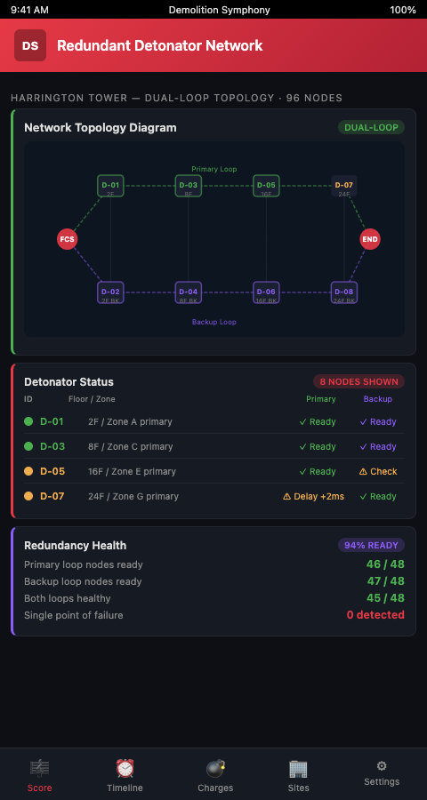
The Redundancy Architecture for Urban Implosion Firing Networks
Think of a redundant detonation timing network as a musical score performed by two independent orchestras simultaneously. Both orchestras read the same score and fire the same notes at the same times. If one orchestra's horn section misfires, the other orchestra's horn section still hits the note. The combined output is complete. No gap in the percussion, no missing beat in the brass — the composition lands as written even if one execution path fails.
Layer 1: Electronic detonator circuit testing before connection. Modern Electronic Blasting Initiation Systems (EBIS) provide built-in circuit testing and three-layer protection — circuit continuity testing, resistance verification, and detonator identification confirmation. EBIS provides built-in circuit testing and three-layer protection. Before the trunk line is connected to the firing machine, every detonator in the network should test as continuous, within resistance tolerance, and correctly identified in the firing sequence. This is not redundancy — it is verification that the primary circuit is complete. Redundancy sits above this.
Layer 2: Dual-initiator placement per critical charge location. For charge positions whose failure would most severely affect the collapse sequence — corner columns, core wall sections, transfer beams — install two initiators: one electronic delay detonator and one non-electric shock tube initiator. The shock tube detonator fires from a separate trunk line and functions as the redundant initiator if the EDD fails. Shock-tube systems provide immunity to electrical interference and are used as redundant backups. The two initiators are timed to the same nominal delay interval; if the EDD fires, the shock tube is a duplicate that reinforces the initiation. If the EDD fails, the shock tube fires independently.
Layer 3: Redundant trunk line routing. A single trunk line running from the blasting machine to the floor blocks is a single point of failure. Route two independent trunk lines — physically separated by at least the distance between opposite ends of the building — connecting to each floor block. If construction debris, a falling facade element, or a connection failure severs one trunk line, the other carries the firing signal. The two trunk lines connect to the same floor-level distribution network but enter from opposite sides.
Step 4: Define the misfire protocol before the shot. The question "what do we do if floor 22 does not fire" must have a written answer before the shot begins, reviewed and signed by the responsible engineer and the firing supervisor. The misfire protocol specifies wait times, approach procedures, and communication requirements. A quantitative reliability analysis comparing pyrotechnic versus electronic detonators justifies dual-system redundancy — but the reliability numbers only protect you if the misfire response is pre-planned.
Map the redundancy architecture in the Demolition Symphony Planner score. Each floor block in the visual score shows which charge locations have dual initiators, which trunk line route connects to each block, and which delay intervals are covered by shock tube backup. When you can see the redundancy architecture on the same floor-by-floor score as the timing sequence, you can verify that no critical charge location is covered by a single initiator — before the wiring begins. The connection to delay detonator sequencing for progressive collapse control is direct: the delay intervals that control the collapse mechanism are also the intervals most critical to protect with redundant initiation.
Advanced Tactics: System Selection, Cost Trade-offs, and Documentation
Balance redundancy depth with network complexity. More redundant pathways reduce misfire risk but increase wiring complexity, which increases installation time and introduces more connection points that can fail. A military-origin reference on redundant explosive train design establishes the principle that the redundancy architecture should be designed to the criticality of each node — not applied uniformly across all initiators. Identify the five to ten charge locations whose failure would most severely compromise the collapse sequence, and concentrate dual-initiator placement at those locations.
Assign different personnel to primary and backup circuit installation. If the same technician wires both the primary EDD and the backup shock tube at a given location, they may replicate the same installation error in both circuits. Requiring two different technicians to handle the two initiation systems at each critical location means that a systematic installation error is less likely to affect both circuits simultaneously.
Connect redundancy planning to millisecond timing precision requirements. The timing precision that progressive collapse control requires — typically within 1-2 milliseconds for electronic detonators — is only achievable if the initiation circuit delivers the firing signal without delay. A backup shock tube system fires with pyrotechnic delay accuracy of ±50 milliseconds, which is insufficient for primary timing control but adequate for backup initiation — the goal being that the charge fires, not that it fires with millisecond precision. Design the backup system for initiation coverage, not timing precision.
Integrate redundancy verification into the pre-shot checklist. The firing sequence plan should include a mandatory pre-shot verification step confirming that each dual-initiator location has been tested, both trunk lines have been continuity-checked, and the misfire protocol document is on-site and signed. This step happens after wiring is complete but before the exclusion zone is established. If verification identifies any gap, the issue is resolved before personnel are cleared from the structure.
Apply the same dual-pathway logic to the sequential strip-out process in industrial decommissioning. In sequential decommissioning, the equivalent of a "misfire" is a failed isolation step — a valve that does not close, a circuit breaker that does not open. Redundant verification steps in each isolation protocol serve the same function as dual initiators: they catch failures before the downstream consequence has already happened.
Document the redundancy architecture in the permit submission. Regulatory reviewers processing an urban implosion permit are evaluating the risk management framework, not just the technical specifications. A permit submission that explicitly identifies which charge locations have dual-initiator coverage, which trunk line routing was used, and what the misfire protocol states gives the reviewer confidence that the project team has modeled the failure modes and built the engineering controls before the shot — not after.
Wire Every Critical Note with a Backup
Demolition Symphony Planner gives urban high-rise implosion coordinators a visual firing network map where redundant initiator coverage and trunk line routing are documented at the same level of detail as delay intervals and charge weights. Join the waitlist to see how the redundancy architecture integrates with your full implosion score — and eliminate the single-initiator gaps that create misfire risk in dense urban environments.
The backup detonation circuit planning workflow described above — dual initiators at critical charge locations, redundant trunk line routing, and documented misfire protocols — represents the minimum standard for a fail-safe blast network design on a 40-story urban implosion. In dense urban environments where a partial misfire means a partially collapsed building in the middle of an occupied city block, redundant initiator systems implosion planning is not belt-and-suspenders engineering. It is the engineering control that closes the gap between the 0.03% misfire rate and the consequence of that failure in a 400-initiator network. Build the redundancy architecture in the score before the wiring crew arrives, and every dual-initiator location has a documented coverage plan before the first circuit is connected.